Best Design for Hvac System in a L Shaped House
![]() Open up access peer-reviewed chapter
Open up access peer-reviewed chapter
Types of HVAC Systems
Submitted: Feb 24th, 2018 Reviewed: May 19th, 2018 Published: November 5th, 2018
DOI: ten.5772/intechopen.78942
From the Edited Volume
HVAC System
Edited by Mohsen Sheikholeslami Kandelousi

IntechOpen Downloads
eleven,318
Total Chapter Downloads on intechopen.com
![]()
Altmetric score
Overall attending for this chapters
Abstract
HVAC systems are milestones of building mechanical systems that provide thermal condolement for occupants accompanied with indoor air quality. HVAC systems tin exist classified into cardinal and local systems according to multiple zones, location, and distribution. Primary HVAC equipment includes heating equipment, ventilation equipment, and cooling or air conditioning equipment. Central HVAC systems locate away from buildings in a central equipment room and deliver the conditioned air by a delivery ductwork system. Central HVAC systems contain all-air, air-h2o, all-water systems. 2 systems should be considered equally central such as heating and cooling panels and water-source estrus pumps. Local HVAC systems can be located inside a conditioned zone or adjacent to it and no requirement for ductwork. Local systems include local heating, local air-conditioning, local ventilation, and split systems.
Keywords
- HVAC systems
- central HVAC systems
- local HVAC systems
- heating systems
- air-conditioning systems
*Address all correspondence to: shaimaa.seyam@mail.utoronto.ca
1. Introduction
Heating, ventilation, and air conditioning (HVAC) arrangement is designed to accomplish the environmental requirements of the condolement of occupants and a process.
HVAC systems are more used in different types of buildings such as industrial, commercial, residential and institutional buildings. The main mission of HVAC system is to satisfy the thermal comfort of occupants by adjusting and changing the outdoor air weather to the desired conditions of occupied buildings [i]. Depending on outdoor weather condition, the outdoor air is drawn into the buildings and heated or cooled before it is distributed into the occupied spaces, then information technology is wearied to the ambient air or reused in the arrangement. The selection of HVAC systems in a given edifice will depend on the climate, the age of the edifice, the individual preferences of the possessor of the edifice and a designer of a project, the project budget, the architectural pattern of the buildings [1].
HVAC systems tin be classified according to necessary processes and distribution process [2]. The required processes include the heating process, the cooling process, and ventilation process. Other processes can be added such as humidification and dehumidification process. These process tin can be achieved past using suitable HVAC equipment such equally heating systems, air-conditioning systems, ventilation fans, and dehumidifiers. The HVAC systems need the distribution organisation to deliver the required amount of air with the desired environmental condition. The distribution system mainly varies according to the refrigerant blazon and the delivering method such as air handling equipment, fan coils, air ducts, and water pipes.
Advertisement
ii. HVAC system selection
Organization selection depends on 3 primary factors including the building configuration, the climate atmospheric condition, and the owner want [two]. The pattern engineer is responsible for because various systems and recommending more 1 system to run into the goal and satisfy the owner of a building. Some criteria can be considered such as climatic change (e.yard., temperature, humidity, and space pressure), edifice chapters, spatial requirements, price such equally majuscule cost, operating cost, and maintenance cost, life cycle analysis, and reliability and flexibility.
However, the selection of a system has some constraints that must be determined. These constraints include the available capacity according to standards, edifice configuration, bachelor infinite, construction upkeep, the bachelor utility source, heating and cooling building loads.
Advertisement
three. Basic components of an HVAC system
The bones components or equipment of an HVAC organization that delivers conditioned air to satisfy thermal comfort of space and occupants and the achieve the indoor air quality are listed below [iii]:
-
Mixed-air plenum and outdoor air control
-
Air filter
-
Supply fan
-
Exhaust or relief fans and an air outlet
-
Outdoor air intake
-
Ducts
-
Terminal devices
-
Return air system
-
Heating and cooling coils
-
Self-contained heating or cooling unit
-
Cooling tower
-
Boiler
-
Control
-
Water chiller
-
Humidification and dehumidification equipment
Advertizement
4. Nomenclature of HVAC systems
The major nomenclature of HVAC systems is central system and decentralized or local organization. Types of a arrangement depend on addressing the primary equipment location to be centralized as conditioning unabridged building as a whole unit of measurement or decentralized equally separately conditioning a specific zone as office of a building. Therefore, the air and h2o distribution system should be designed based on system classification and the location of primary equipment. The criteria every bit mentioned above should also be applied in selecting between ii systems. Tabular array 1 shows the comparison of fundamental and local systems according to the pick criteria [3, 4].
| Criteria | Key system | Decentralized system |
|---|---|---|
| Temperature, humidity, and space pressure requirements | Fulfilling any or all of the design parameters | Fulfilling any or all of the design parameters |
| Capacity requirements |
|
|
| Redundancy | Standby equipment is accommodated for troubleshooting and maintenance | No backup or standby equipment |
| Special requirements |
|
|
| Start cost |
|
|
| Operating cost |
|
|
| Maintenance toll | Accessible to the equipment room for maintenance and saving equipment in fantabulous condition, which saves maintenance cost | Accessible to equipment to be located in the basement or the living space. However, it is difficult for roof location due to bad weather |
| Reliability | Central system equipment tin be an attractive benefit when considering its long service life | Reliable equipment, although the estimated equipment service life may be less |
| Flexibility | Selecting standby equipment to provide an alternative source of HVAC or backup | Placed in numerous locations to be more flexible |
Table 1.
Comparison of central and local HVAC systems.
Advertisement
5. HVAC arrangement requirements
Four requirements are the bases for any HVAC systems [4]. They need primary equipment, space requirement, air distribution, and pipe, as shown in Figure 1.
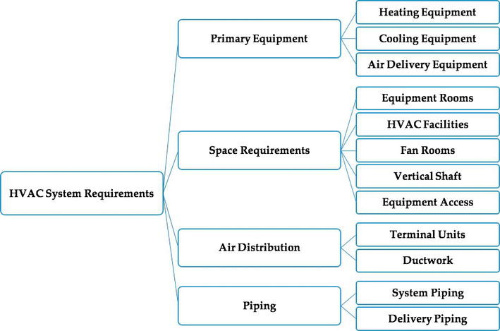
Figure 1.
Horizontal bureaucracy representation of HVAC system requirements.
Primary equipment includes heating equipment such as steam boilers and hot water boilers to heat buildings or spaces, air delivery equipment equally packaged equipment to deliver conditioned ventilation air by using centrifugal fans, axial fans, and plug or plenum fans, and refrigeration equipment that delivers cooled or conditioned air into space. It includes cooling coils based on water from h2o chillers or refrigerants from a refrigeration process.
Space requirement is essential in shaping an HVAC organisation to exist fundamental or local. Information technology requires v facilities as the post-obit:
-
Equipment rooms: since the total mechanical and electric space requirements range betwixt four and 9% of the gross building expanse. It is preferable to be centrally located in the building to reduce the long duct, piping, and conduit runs and sizes, to simplify shaft layouts, and centralized maintenance and operation.
-
HVAC facilities: heating equipment and refrigeration equipment require many facilities to perform their chief tasks of heating and cooling the building. The heating equipment requires banality units, pumps, heat exchangers, pressure-reducing equipment, control air compressors, and miscellaneous equipment, while the refrigeration equipment requires water chillers or cooling water towers for large buildings, condenser water pumps, oestrus exchangers, air-conditioning equipment, command air compressors, and miscellaneous equipment. The design of equipment rooms to host both pieces of equipment should consider the size and the weight of equipment, the installation and maintenance of equipment, and the applicable regulations to combustion air and ventilation air criteria.
-
Fan rooms contain the HVAC fan equipment and other miscellaneous equipment. The rooms should consider the size of the installation and removal of fan shafts and coils, the replacement, and maintenance. The size of fans depends on the required air period rate to condition the building, and it can be centralized or localized based on the availability, location, and toll. Information technology is preferable to have like shooting fish in a barrel access to outdoor air.
-
Vertical shaft: provide space for air distribution and h2o and steam pipage distribution. The air distribution contains HVAC supply air, exhaust air, and render air ductwork. Piping distribution includes hot water, chilled h2o, condenser water, and steam supply, and condenser return. The vertical shaft includes other mechanical and electrical distribution to serve the entire edifice including plumbing pipes, burn down protection pipes, and electrical conduits/closets.
-
Equipment access: the equipment room must let the move of large, heavy equipment during the installation, replacement, and maintenance.
Air distribution considers ductwork that delivers the conditioned air to the desired area in a direct, quiet, and economical fashion every bit possible. Air distribution includes air terminal units such equally grilles and diffusers to deliver supply air into a space at low velocity; fan-powered terminal units, which uses an integral fan to ensure the supply air to the space; variable air volume terminal units, which deliver variable amount of air into the space; all-air induction terminal units, which controls the primary air, induces return air, and distributes the mixed air into a space; and air-h2o induction last units, which contains a curlicue in the induction air stream. All the ductwork and pipe should be insulated to prevent oestrus loss and save building free energy. It is likewise recommended that buildings should accept enough ceiling spaces to host ductwork in the suspended ceiling and floor slab, and tin can be used as a return air plenum to reduce the return ductwork.
The piping system is used to deliver refrigerant, hot water, cooled water, steam, gas, and condensate to and from HVAC equipment in a direct, serenity and affordable way. Pipage systems can be divided into two parts: the piping in the key plant equipment room and the delivery piping. HVAC pipage may or may not be insulated based on existing code criteria.
Advertisement
6. Cardinal HVAC systems
A cardinal HVAC arrangement may serve one or more than thermal zones, and its major equipment is located outside of the served zone(southward) in a suitable central location whether inside, on top, or adjacent to the edifice [4, 5]. Central systems must status zones with their equivalent thermal load. Central HVAC systems will accept as several command points such as thermostats for each zone. The medium used in the command organisation to provide the thermal free energy sub-classifies the central HVAC arrangement, as shown in Effigy ii.
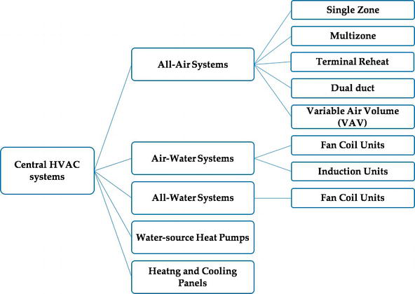
Figure 2.
Horizontal bureaucracy representation of the chief types of fundamental HVAC systems.
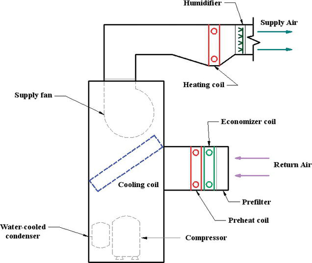
The thermal energy transfer medium can exist air or h2o or both, which represent as all-air systems, air-water systems, all-water systems. Also, cardinal systems include water-source heat pumps and heating and cooling panels. All of these subsystems are discussed below. Central HVAC system has combined devices in an air treatment unit, as shown in Effigy iii, which contains supply and return air fans, humidifier, reheat ringlet, cooling curl, preheat gyre, mixing box, filter, and outdoor air.
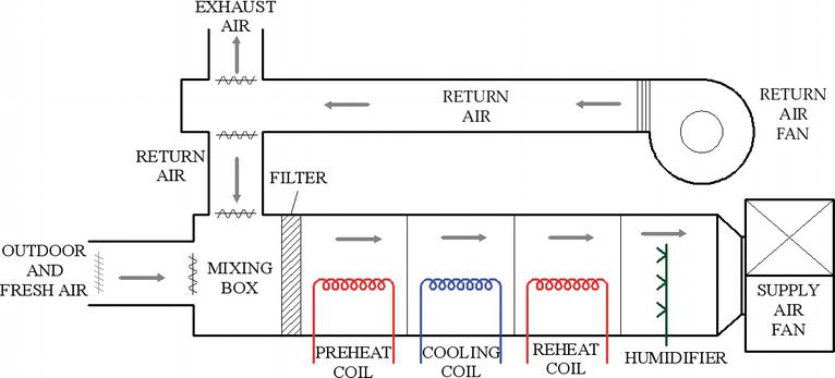
Figure 3.
Equipment arrangement for central HVAC arrangement.
6.1. All-air systems
The thermal energy transfer medium through the building delivery systems is air. All-air systems can be sub-classified based on the zone equally single zone and multizone, airflow rate for each zone as constant air book and variable air volume, terminal reheat, and dual duct [5].
6.i.1. Single zone
A single zone system consists of an air handling unit of measurement, a estrus source and cooling source, distribution ductwork, and advisable commitment devices. The air treatment units can be wholly integrated where heat and cooling sources are bachelor or separate where heat and cooling source are discrete. The integrated parcel is nigh-usually a rooftop unit and connected to ductwork to evangelize the conditioned air into several spaces with the same thermal zone. The main advantage of single zone systems is simplicity in design and maintenance and depression get-go cost compared to other systems. However, its main disadvantage is serving a single thermal zone when improperly practical.
In a single zone all-air HVAC system, ane control device such every bit thermostat located in the zone controls the operation of the system, as shown in Effigy 4. Control may exist either modulating or on–off to meet the required thermal load of the single zone. This can exist accomplished by adjusting the output of heating and cooling source within the packaged unit.
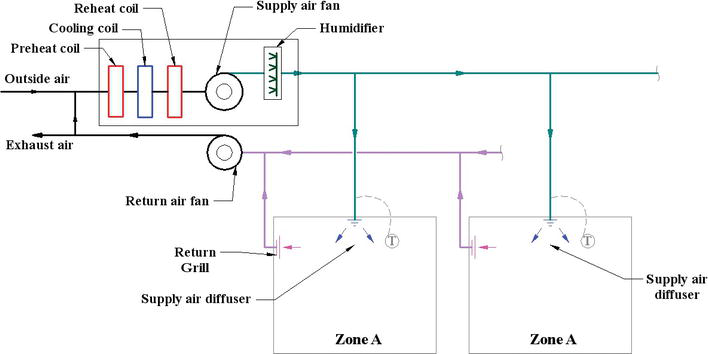
Figure 4.
All-air HVAC system for single zone.
Although few buildings can be a unmarried thermal zone, a unmarried zone can be found in several applications. 1 family residential buildings can exist treated every bit single zone systems, while other types of residential buildings tin include unlike thermal free energy based on the occupation and building construction. Movements of occupants affect the thermal load of the edifice, which results in dividing the building into several single zones to provide the required environmental condition. This tin be observed in larger residences, where two (or more than) single zone systems may be used to provide thermal zoning. In low-rise apartments, each flat unit may exist conditioned by a separate single zone organisation. Many sizeable single story buildings such every bit supermarkets, discount stores, can be effectively conditioned by a serial of unmarried zone systems. Large office buildings are sometimes conditioned past a serial of carve up unmarried zone systems.
6.1.2. Multi-zone
In a multi-zone all-air system, private supply air ducts are provided for each zone in a building. Cold air and hot (or render) air are mixed at the air handling unit to achieve the thermal requirement of each zone. A item zone has its conditioned air that cannot be mixed with that of other zones, and all multiple zones with different thermal requirement demand separate supply ducts, as shown in Figure 5. Multi-zone all-air system consists of an air handling unit with parallel menstruation paths through cooling coils and heating coils and internal mixing dampers. Information technology is recommended that i multi-zone serve a maximum of 12 zones because of concrete restrictions on duct connections and damper size. If more than zones are required, boosted air handlers may exist used. The advantage of the multi-zone organization is to adequately condition several zones without free energy waste material associated with a terminal reheat system. However, leakage between the decks of air handler may reduce energy efficiency. The main disadvantage is the need for multiple supply air ducts to serve multiple zones.
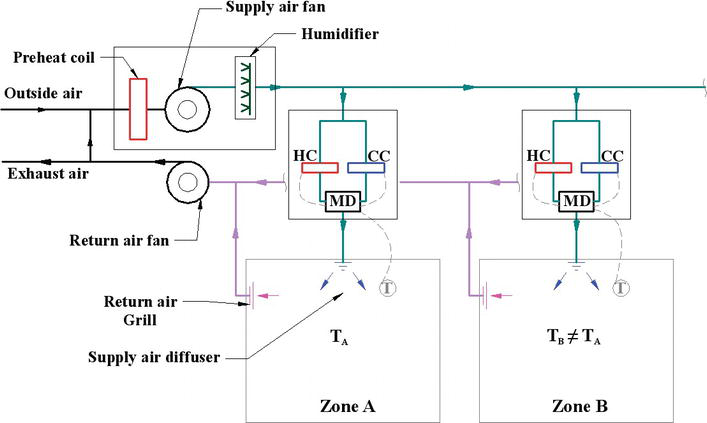
Effigy 5.
All-air HVAC system for multiple zones.
vi.1.3. Terminal reheat
A terminal reheat all-air system is a multiple zone, which considers an adaptation of single zone system, equally shown in Figure six. This can be performed by adding heating equipment, such as hot water coil or electric roll, to the downstream of the supply air from air handling units most each zone. Each zone is controlled past a thermostat to adjust the heat output of heating equipment to encounter the thermal condition. The supply air from air handling units is cooled to the lowest cooling signal, and the terminal reheat adds the required heating load. The advantage of final reheat is flexible and can be installed or removed to accommodate changes in zones, which provides improve command of the thermal conditions in multiple zones. However, the design of terminal reheat is not energy-efficient organisation because a significant amount of extremely cooling air is not regularly needed in zones, which can be considered as waste free energy. Therefore, energy codes and standards regulate the utilise of reheat systems.
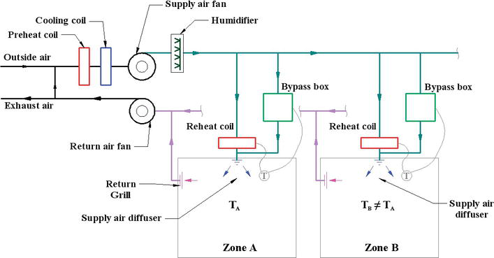
Figure half-dozen.
Unmarried duct organisation with reheat terminal devices and bypass units.
vi.1.four. Dual duct
The dual duct all-air organisation is a terminal-controlled modification of the multi-zone concept. A central air treatment unit of measurement provides two conditioned air streams such every bit a cold deck and a hot deck, as shown in Figure vii. These air streams are distributed throughout the expanse served by the air handling unit in divide and parallel ducts. Each zone has a terminal mixing box controlled by zone thermostat to adapt the supply air temperature by mix the supply cold and hot air. This blazon of system volition minimize the disadvantages of previous systems and become more flexible past using terminal control.
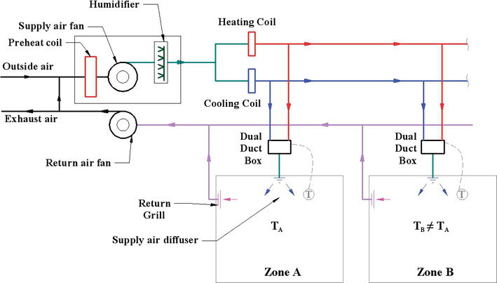
Effigy 7.
All-air HVAC dual-duct system.
vi.1.5. Variable air book
Some spaces require different airflow of supply air due to the changes in thermal loads. Therefore, a variable-air-volume (VAV) all-air organization is the suitable solution for achieving thermal comfort. The previous four types of all-air systems are constant book systems. The VAV system consists of a central air treatment unit which provides supply air to the VAV terminal command box that located in each zone to adjust the supply air volume, as shown in Figure 8. The temperature of supply air of each zone is controlled by manipulating the supply air menstruum charge per unit. The main disadvantage is that the controlled airflow rate can negatively impact other adjacent zones with different or like airflow rate and temperature. Besides, part-load conditions in buildings may require low air-flow rate which reduces the fan power resulting in free energy savings. It may also reduce the ventilation menses rate, which can be problematic to the HVAC system and affecting the indoor air quality of the edifice.
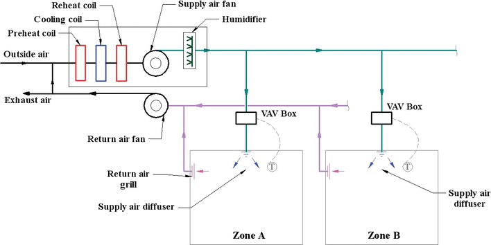
Figure eight.
All-air HVAC systems with VAV last units.
6.2. All-h2o systems
In an all-water system, heated and cooled water is distributed from a central system to conditioned spaces [four, 5]. This type of system is relatively small compared to other types because the utilise of pipes equally distribution containers and the water has higher heat capacity and density than air, which requires the lower volume to transfer oestrus. All-h2o heating-just systems include several commitment devices such as floor radiators, baseboard radiators, unit of measurement heaters, and convectors. All the same, all-water cooling-only systems are unusual such as valance units mounted in the ceiling. The primary type that is used in buildings to status the unabridged infinite is a fan-curl unit of measurement.
6.two.1. Fan-curl units
Fan-gyre unit is considerably pocket-sized unit used for heating and cooling coils, circulation fan, and proper control system, every bit shown in Figure ix. The unit tin can be vertically or horizontally installed. The fan-coil unit tin be placed in the room or exposed to occupants, so it is essential to take appropriate finishes and styling. For central systems, the fan-coil units are continued to boilers to produce heating and to water chillers to produce cooling to the conditioned space. The desired temperature of a zone is detected past a thermostat which controls the water period to the fan-coil units. In addition, occupants can adjust fan coil units past adjusting supply air louvers to accomplish the desired temperature. The main disadvantage of fan-coils is ventilation air and only tin can be solved if the fan-coil units are connected to outdoor air. Another disadvantage is the noise level, especially in critical places.
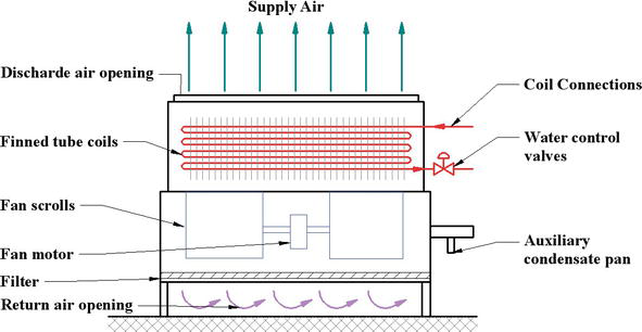
Figure 9.
All-h2o system: fan-coil units.
half-dozen.three. Air-water systems
Air-h2o systems are introduced as a hybrid organisation to combine both advantages of all-air and all-water systems [5]. The volume of the combined is reduced, and the outdoor ventilation is produced to properly status the desired zone. The water medium is responsible for carrying the thermal load in a edifice by lxxx–xc% through heating and cooling h2o, while air medium atmospheric condition the residuum. There are ii master types: fan-coil units and induction units.
half dozen.3.ane. Fan-coil units
Fan-coil units for air-water systems are like to that of all-water systems except that the supply air and the conditioned water are provided to the desired zone from a key air handling unit and fundamental water systems (e.g., boilers or chillers). The ventilation air can be separately delivered into space or continued to the fan-roll units. The major types of fan-coil systems, are 2 pipes or 4-pipes systems, as shown in Figure x.
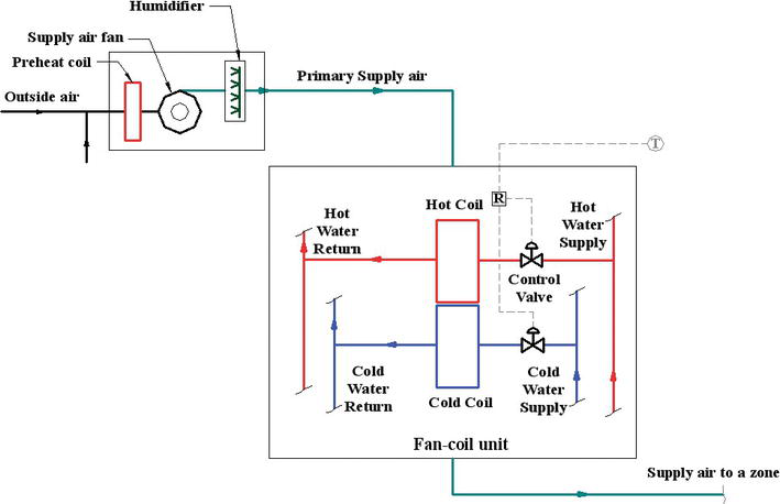
Figure x.
Air-water HVAC organisation using fan coil units with 4-pipes configuration.
6.3.ii. Induction units
Consecration units are externally similar to fan-curlicue units but internally dissimilar. An induction unit induces the air menstruation in a room through cabinet by using high-velocity airflow from a central air handling unit, which replaces the forced convection of the fan in the fan-curlicue past the induction or buoyancy effect of the induction unit, as shown in Effigy eleven. This tin can be performed equally mixing the primary air from the central unit of measurement and the secondary air from the room to produce a suitable and conditioned air into the room/zone.
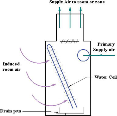
Figure 11.
Air-water HVAC system using induction units.
6.4. Water-source heat pumps
H2o-source heat pumps are used to provide considerable energy savings for large building under the extreme cold weather [6]. A building of various zones can be conditioned by several individual heat pumps since each rut pump tin can be controlled according to the zone control. A centralized h2o circulation loop can be used as a oestrus source and heat sink for heat pumps. Therefore, heat pumps can act as the primary source of heating and cooling. The master disadvantage is the lack of air ventilation similar to the all-water systems equally in fan-coil units. For a heating process, the boiler or solar collectors will be used to supply rut to the water circulation, while a cooling tower is used to turn down heat nerveless from the oestrus pumps to the atmosphere. This system does non use chillers or any refrigeration systems. If a building requires a heating process for zones and cooling process for other zones at the same time, the heat pump volition redistribute heat from one part to some other with no demand for a boiler or cooling tower operation,
6.5. Heating and cooling panels
Heating and cooling panels are placed on floors or walls or ceilings where can be a source of heating and cooling [vii]. It besides can be called as radiant panels. This type of system tin be constructed equally tubes or pipes impeded inside the surface where the cooling or heating media is circulated into the tubes to cool or heat the surface. The tubes are contacted to the side by side large expanse to reach the desired surface temperature for cooling and heating procedure. The heat transfer process is mainly by the radiation mode between the occupants and the radiant panels, and the natural convection fashion between the air and panels. Temperature restriction is recommended for radiant floor panels, a range of 66–84°F, to achieve thermal comfort for occupants (ASHRAE Standard 55). Radiant ceiling or wall panels can be used for cooling and heating process. The surface temperature should exist higher than the air dew point temperature to avoid condensation on the surface during the cooling process. Also, the maximum surface temperature is 140°F for ceiling levels at 10 ft. and 180°F for ceiling levels at 18 ft. This temperature is recommended to avoid besides much heating above occupants' heads.
The installation of such systems is often expensive compared to other types as mentioned in a higher place, but they tin can be useful and has a lower running cost mainly because of the surface temperature restriction. A command indicate is connected to the thermostat of each zone to dispense the medium temperature to condition the space. The used medium can be refrigerant or h2o mixing with inhibited glycol (anti-freeze) instead of manifestly water to prevent icing inside the tubes for the cooling procedure. The master reward is no space required, simply a few inches for the panels to be installed and no more collected clay in the standard ceiling or the ductwork. Many designs are available to produce attractive panels.
Advertisement
7. Local HVAC systems
Some buildings tin have multiple zones or have a large, unmarried zone, which needs fundamental HVAC systems to serve and provide the thermal needs [4, 5]. However, other building may have a single zone which needs equipment located within the zone itself, such as pocket-sized houses and residential apartments. This type of organization is considered as local HVAC systems since each equipment serving its zone without crossing boundaries to other adjacent zones (e.chiliad., using an air conditioner to cool down a bedroom, or using an electrical heater for the living room). Therefore, a unmarried zone requires but one-point control point connected to a thermostat to activate the local HVAC organisation. Some buildings have multiple local HVAC systems as proper equipment serving specific single zones and controlled past the one-betoken control of the desired zone. Yet, these local systems are non connected and integrated to key systems, but nonetheless function of a large full-building HVAC systems. There are many types of local HVAC systems equally shown in Figure 12.
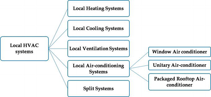
Effigy 12.
Horizontal hierarchy representation of the primary types of local HVAC systems.
vii.1. Local heating systems
A unmarried zone will require a complete, single package of heating system which contains heat source and distribution arrangement. Some examples include portable electric heaters, electric resistance baseboard radiators, fireplaces and woods stoves, and infrared heaters [8].
vii.2. Local cooling systems
Local cooling systems can include agile systems as air-conditioning systems that provide cooling, a proper air distribution inside a zone, and command of humidification, and natural systems as convective cooling in open up window, evaporative cooling in fountains [five, 6].
7.three. Local ventilation systems
Local ventilation systems tin can be forced systems by using devices such as window fan to let air movement betwixt outdoor and a single zone without changing in the thermal environment of the zone. Other systems used for ventilation are air circulation devices such as desk or paddle fans to better thermal comfort of the space by allowing the heat to be transferred past conventional mode [5, 6].
seven.4. Local ac systems
A local ac organisation is a complete package that tin incorporate cooling and heating source, a circulation fan, a filter, and command devices. In that location are three main types listed below [five, 6].
seven.four.i. Window air-conditioner
This organization is a packaged device consisting of a vapor pinch refrigeration cycle that contains a compressor, a condenser, an expansion valve, and an evaporator, in addition to a fan, a filter, control organisation and housing. Window air-conditioners can be installed in a framed or unframed opening in building walls and in window openings without any ductwork and distribution the cooling or heating air effectively inside the conditioned space. The air conditioning contains both evaporator and condenser where the condenser is located exterior the infinite while the evaporate is inside the space, nonetheless, it serves the entire single zone with the thermal requirements. The heating procedure can be achieved by adding electric resistance coil in the air workout or reversing the refrigeration cycle to human action as a heat pump. Many feature designs are produced to provide aesthetical values and better the quality and response.
7.iv.two. Unitary air-conditioner
It is similar to window air conditioners from the equipment perspective, merely it is designed for commercial buildings. It is installed on the exterior wall of the edifice and generally located almost the floor-wall intersection, as shown in Figure thirteen. Every single zone will contain one unitary air-conditioner as in each guest room in many hotels.
Effigy thirteen.
Unitary air-conditioner package.
7.4.3. A packaged rooftop air-conditioner
It consists of a vapor pinch refrigeration wheel; heat source such as heat pump and electric resistance; an air handler such as dampers, filter, and fan; and command devices, as shown in Effigy 14. This organisation may exist connected to ductwork and serve a big-size single zone that cannot be served by unitary or window air conditioners.
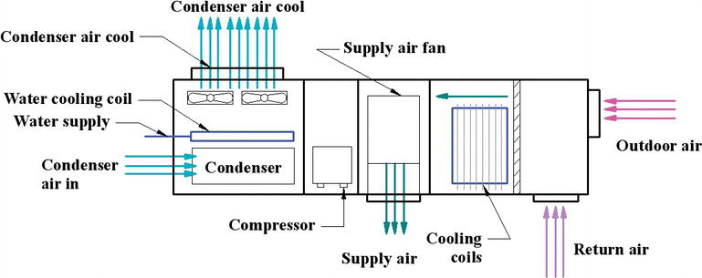
Figure 14.
Packaged rooftop air-conditioning unit of measurement.
7.five. Split systems
The divide systems contain ii central devices [5, 6]: the condenser, located outdoor, and the evaporator, located indoors. The ii devices are connected by a conduit for refrigerant lines and wiring. This system solves some problems of minor-scale single-zone systems since the location and installation of window, unitary or rooftop air conditioners may touch the esthetic value and architectural design of the building. The carve up systems can comprise one condenser unit of measurement and connected to multiple evaporator units to serve multiple zones as possible under same conditions or different environmental conditions.
Advertizement
8. Conclusions
This chapter presents the types of HVAC systems. HVAC systems have several requirements including principal equipment such as heating equipment, cooling equipment, and commitment equipment; space requirement such as HVAC facilities, equipment room, and vertical shaft; air distribution; and piping. Type of HVAC systems tin be divided into central HVAC systems and local HVAC systems. This classification depends on zone types and the location of HVAC equipment. The central HVAC systems can serve multiple and single zones and locate away from the building, which needs distribution devices. They also tin be sub-classified into all-air HVAC systems, air-water systems, all-water systems, h2o-source heat pumps, and heating and cooling console systems. The local HVAC systems are mostly placed within or next to the living spaces and serve one single zone. They consist of local heating systems, local ac systems, local ventilation systems, and split systems.
References
- 1.
ASHRAE Handbook. HVAC Systems and Equipment. Atlanta, GA: American Society of Heating, Refrigerating, and Air Conditioning Engineers; 1996. pp. ane-ten - ii.
American Society of Heating, Refrigerating & Air-conditioning Engineers. Heating, Ventilating, and Air-Conditioning: Systems and Equipment: 2000 ASHRAE Handbook: Inch-Pound. Amer Society of Heating; 2000 - iii.
Sugarman SC. HVAC Fundamentals. 2nd ed. CRC Press, The Fairmont Press, Inc.; 2005 - 4.
American Society of Heating, Refrigerating & Air-Conditioning Engineers. ASHRAE Handbook. Fundamentals: SI ed. Amer Society of Heating, Atlanta, GA; 2009 - 5.
Haines RW, Myers ME. HVAC Systems Design Handbook. McGraw-Loma Educational activity; 2010 - 6.
ASHRAE Handbook. Fundamentals. Atlanta: American Order of Heating, Refrigerating and Air-conditioning Engineers; 2001. p. 111 - seven.
Mumma SA. Ceiling console cooling systems. ASHRAE Periodical. 2001; 43 (11):28 - eight.
Brumbaugh JE. Audel HVAC Fundamentals: Volume 1: Heating Systems, Furnaces, and Boilers. Vol. 17. Canada: John Wiley & Sons, Wiley Publishing, Inc.; 2004
Submitted: Feb 24th, 2018 Reviewed: May 19th, 2018 Published: November fifth, 2018
© 2022 The Author(s). Licensee IntechOpen. This affiliate is distributed under the terms of the Creative Commons Attribution 3.0 License, which permits unrestricted use, distribution, and reproduction in any medium, provided the original work is properly cited.
Source: https://www.intechopen.com/chapters/62059